Maraytr - Marek's Ray-tracer
4 Ray tracer
Turning ray-caster to ray-tracer is done by adding secondary rays that are able to compute shadows and reflections.
4.1 Lights and shadows
The simplest light is a point light because from any point you either see it or not. Point light casts hard shadows. Computing whether a point is lit by a point light is very simple — just cast a ray from the point to the light. If the ray hits anything then the original point is in shadow. Otherwise we can compute light intensity based on the distance and normal angle. I use basic Phong reflection model for that. Example of one point light in a scene is in Figure 1
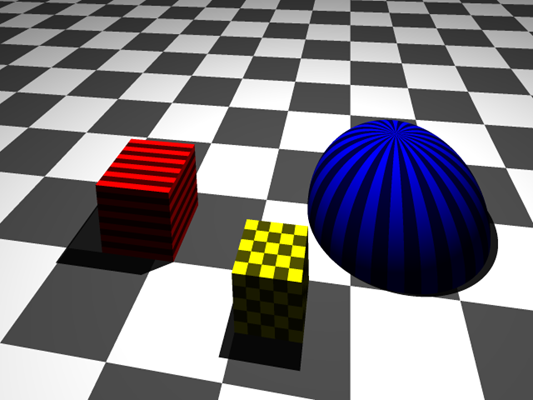
Example of simple scene a point light casting hard shadows.

Figure 1: Example of simple scene a point light casting hard shadows.
Area lights are usually simulated as an array of point lights. For every pixel we have to cast multiple rays to all point lights in area light source.
This is starting to be very computationally expensive. To lower the load it is possible to connect light sampling with sub-pixel sampling (this technique is called Super-sampling). Say, we are casting 16 sub-pixel rays per pixel to make the result image smooth. In the scene we have an area light that is made of also 16 point lights. Now to compute lighting for every pixel we need 16∙16 = 256 rays. However, we can combine the two integrations together and send sub-pixel-ray number i to only one sub-point-light number i (not to all of them). This will result in only 2∙16 = 32 rays. This is why you can find IntegrationState information passed to the light source.
Figure 2 shows area light with described optimized sampling technique. You can see shadow artifacts from roughly four levels. This is because the area light is 4x4 point lights perfectly aligned in a grid. The artifacts can be reduced by using jittering.
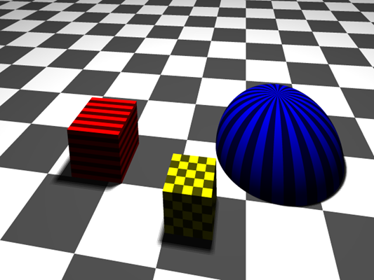
Example of area light casting (somewhat) soft shadows.

Figure 2: Example of area light casting (somewhat) soft shadows.
4.2 Reflections and refractions
Reflections (and refractions) are little more complicated than lights. Refractions are very similar to reflections and I will describe only reflections here.
Every object has to have information about how much reflective it is. This information is accessible through ReflectionFactor property in IMaterial (Code listing 1). Now the real ray-tracing begins.
Code listing 1: IMaterial interface.
1 2 3 4 5 | public interface IMaterial { ColorRgbt BaseColor { get; } ITexture Texture { get; } float ReflectionFactor { get; } } |
First a primary ray is casted and intersection is obtained. Then, secondary ray is cast if the reflection factor is greater than a limit (close to zero). The direction of reflected ray is given by standard reflection model based on the surface normal. The ray may be bouncing many times around the scene. The important thing is to keep track of total contribution and stop the bouncing if the contribution is too low. For example, imagine two 50% mirrors. First bounce will have 50% contribution, second 25% (50% of 50%), third 12.5% (50% of 25%), etc. Sum of all colors multiplied by their contributions gives the final color.
Recursion provides a great way to achieve this process. Code listing 2 shows the method that computes the described ray-tracing. This is a core of the ray-tracer.
Code listing 2: Ray-tracing core.
1 2 3 4 5 6 7 8 9 10 11 12 13 14 15 16 17 18 19 20 | ColorRgbt traceRay(Ray ray, IntegrationState intState, int depth, double contribution) { var isec = getIntersection(ray); if (isec == null) { return scene.BgColor; } ColorRgbt color = evaluateIntersection(isec, intState); contribution *= isec.Material.ReflectionFactor; if (depth >= MaxTraceDepth || contribution < MinContribution) { return color; } Vector3 reflectedDir = computeReflection(isec.Normal, -ray.Direction); reflectedDir.NormalizeThis(); ColorRgbt reflectedColor = traceRay(new Ray(isec.Position, reflectedDir), intState, depth + 1, contribution); return color + reflectedColor * isec.Material.ReflectionFactor; } |
The result of reflections is show in Figure 3. The floor has 50% reflectance and all the objects have 30%. The cool thing about reflections is that you can put mirrors in the scene! The mirror in the back of the image has 95% reflectivity and it is tilted in X and Y directions by 10 degrees.
If you look carefully you can see that the yellow cube in front has much worse soft shadow than the red cube. This is caused by not using jittering on the area lights. The samples of the area light are aligned with the yellow cube. Due to the sampling you can see four intensities because the light is made of 4x4 point lights. The red cube is rotated by 30 degrees which result is much smoother shadow.
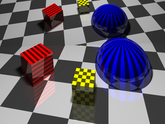
All objects in this scene are reflective. There is a huge mirror in the back of the scene.
