Maraytr - Marek's Ray-tracer
2 Scene representation
The first decision should be made about representation of a scene. There are two main options to consider.
The first option is represent the scene as a bunch of triangles — triangle mesh. This representation is quite convenient, ray-triangle intersection algorithm is simple, and you will be able to download 3D models from internet and load them into your program. The problem is that creating your own shapes is not easy and boolean operations such as intersection and subtraction are hard. Also, texturing is a problem.
The second option is to represent shapes purely procedurally, for example as sphere defined only by center and radius. An example of such scene is shown in Figure 1. Based on this little information one can write a function that computes an intersection between ray and sphere. And the sphere will be mathematically perfect. The advantage of this representation might be ability to do boolean operations easily and procedural texturing is also simple. The biggest disadvantage is that making more complicated shapes is very hard. You have to construct them only using primitive shapes and boolean operations.
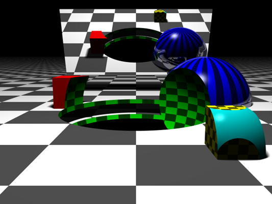
A procedurally created scene containing spheres, cubes, and planes. More complicated shapes are created using boolean operations. The mirror in the back is just a plane intersected with a box and it has 100% reflectivity. Notice the soft shadows and reflection on the blue sphere.

Figure 1: A procedurally created scene containing spheres, cubes, and planes. More complicated shapes are created using boolean operations. The mirror in the back is just a plane intersected with a box and it has 100% reflectivity. Notice the soft shadows and reflection on the blue sphere.
2.1 Constructive solid geometry
I have decided to represent the scene procedurally because it is in my eyes much cooler and also there are more things to play with. However, the design design allows to add triangle meshes support without problems later.
A good way to represent procedural scene is Constructive solid geometry. CSG can be represented as a binary tree where leaves are primitives and internal nodes are operations. Every node have also information about its relative transformation such as rotation or translation. The trick is that the transformation is applied on the ray rather than on the object. This trick can dramatically reduces complexity of intersection functions (more on that later in Section 2.2 CSG primitives).
CSG is actually quite powerful representation because it is volumetric representation. It is used by come CAD programs for designing real-world objects. The more primitive objects you have the more complicated things you can create with them.

CSG objects represented as a binary tree. The ∩ is intersection, ∪ is union, and — is difference (by Zottie from Wikipedia).
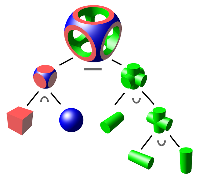
Figure 2: CSG objects represented as a binary tree. The ∩ is intersection, ∪ is union, and — is difference (by Zottie from Wikipedia).
The scene class shown in Code listing 1 contains basic information such as the scene root, camera, and lights. Everything is defined through interfaces to enable easy extensibility.
The scene root can be anything that can be intersected. In our case it will be the node (root) of CSG tree but it is possible to write a class that intersects triangle meshes or anything else.
Code listing 1: Scene class.
1 2 3 4 5 6 7 8 9 10 11 | public class Scene { public IIntersectable SceneRoot { get; set; } public ColorRgbt BgColor { get; set; } public IReflectionModel ReflectionModel { get; set; } public ICamera Camera { get; set; } public ColorRgbt AmbientLight { get; set; } public List<ILightSource> Lights { get; set; } } |
2.2 CSG primitives
The key elements in the CSG representation are primitive shapes. The cool part is that every shape is defined algorithmically by its intersection procedure. Just think about it, there is no actual sphere in the scene, just a piece of program that is able to compute if given ray intersects it or not.
“Wait, and how about center and radius?„
Good question, but nope, we don't need those. As already mentioned, every node in CSG graph contains its transformation. If your intersection method is written to intersect unit sphere with center in origin then you just translate and scale it to get any general sphere. Isn't this cool? All the very basic shapes does not need any information — just the intersection function.
Talking about intersection functions, let's derive the one for a sphere. For the notation, bold symbols are 3D vectors, normal symbols are just scalars. A sphere with center c and radius r can be defined as (x - c)2 = r2. The equation can be interpreted as all points x with distance r from point c. A ray starting in point s going in direction d is a set of points x for which x = s + t∙d. The direction d is unit vector and t is time parameter that specifies a position among the ray. Now we just put the two equations together while setting c = 0 and r = 1.
(x - 0)2 = 12x = s + t∙d(s + t∙d)2 = 1s∙s + 2 t s∙d + t2 d∙d = 1d is unit vector so d∙d = 1t2 + t (2∙s∙d) + (s∙s - 1) = 0t. D = B2 - 4 A C, where Ais 1,Bis 2∙s∙d, andCis s∙s - 1.
D = 4∙(s∙d)2 - 4∙s∙s + 4t1,2 = -B ± D0.5 / 2∙A t1,2 = -s∙d ± ((s∙d)2 - s∙s + 1)0.5 = -s∙d ± (D / 4)0.5a∙b is dot-product: a∙b = Σi ai ∙ bi Equation 9 gives us the solution in terms of two numbers t. We can compute a point of intersections using original ray equation x = s + t∙d. If t is negative then the intersection is in behind us (in opposite direction than direction vector d).
Understanding the math underneath is crucial. For example, we ended up with two solutions, why? Because a ray can intersect a sphere at two points. That makes sense, right?
The math also gives us a hint about some special cases. For example, when D is negative we cannot compute its square root. That actually mean that the ray missed the sphere and there are no intersections. When D is zero then the ray is tangent to the sphere and we have only one intersection.
Turning the math into the code is very simple as you can see in Code listing 2. The only catch is the case with one intersection. We want to have either two intersections or none because intersection represents entering and leaving the volume of the object. So I consider (near) tangent ray as a miss (Section 5.1 CSG operations explains why having intersections paired is important).
Other primitives such as cube and plane are described in similar way. Now we are ready to start shooting some rays!
Code listing 2: Sphere intersection code.
1 2 3 4 5 6 7 8 9 10 11 12 13 14 15 16 17 18 19 20 | public class Sphere : IIntersectableObject { public int Intersect(Ray ray, IList<Intersection> outIntersections) { double sd = ray.StartPoint.Dot(ray.Direction); double ss = ray.StartPoint.Dot(ray.StartPoint); double discrOver4 = sd * sd - ss + 1; if (discrOver4 <= 0.0 || discrOver4.IsAlmostZero()) { return 0; // 0 or 1 solution, but we want two. } double discrOver4Sqrt = Math.Sqrt(discrOver4); double tEnter = -sd - discrOver4Sqrt; double tLeave = -sd + discrOver4Sqrt; Debug.Assert(tEnter < tLeave); outIntersections.Add(new Intersection(this, true, ray, tEnter)); outIntersections.Add(new Intersection(this, false, ray, tLeave)); return 2; } } |
2.3 Transformations
The binary tree structure of the CSG representation also allows to conveniently store transformations. Every node stores a relative (local) transformation from its parent as affine transformation matrix.
Code listing 3 shows CSG node class. Every node has reference to its parent, list of children and a local transformation. The Intersect method have to be implemented by derived class. There are two derived classes: the one representing geometric primitives (leaves) and then the boolean operation nodes (internal nodes). The primitives just compute the intersection with given ray. Interesting stuff happens in the operation nodes and will be described later in Section 5.1 CSG operations.
Code listing 3: CsgNode class.
1 2 3 4 5 6 7 8 9 10 11 12 13 14 15 16 17 18 19 20 | public abstract class CsgNode : IIntersectable { public CsgNode Parent { get; set; } public bool IsRoot { get { return Parent == null; } } protected List<CsgNode> children = new List<CsgNode>(); public IEnumerable<CsgNode> Children { get { return children; } } public bool IsLeaf { get { return children.Count == 0; } } public int ChildrenCount { get { return children.Count; } } public Matrix4Affine LocalTransform { get; set; } public abstract int Intersect(Ray ray, IList<Intersection> outIntersections); public virtual void PrecomputeTransformCaches(Matrix4Affine globalTransform) { var t = globalTransform * LocalTransform; foreach (var child in children) { child.PrecomputeTransformCaches(t); } } } |