Maraytr - Marek's Ray-tracer
3 Ray caster
Now that we know how the scene is represented let's quickly talk about how intersections are computed and then we can finally cast some rays!
3.1 Intersections computation
As described in Section 2.2 CSG primitives the ray intersection method of primitive shapes has no information about position, scale, or rotation of the object. Instead of moving the object itself we move the rays. In order to transform a ray from global coordinate system to local one we have to apply all transformations from current node to the root. It is wasteful to do this costly operation for every ray so method PrecomputeTransformCaches in CsgNode and CsgObjectNode classes pre-computes the transformations.
Transformations and matrix multiplications can be tricky and you may have to spend more time to understand them. I will mention just a few tips here.
First, you have to apply inverse of the object transformation on rays. Imagine this as shooting at a target. Instead of moving the target to the right and hitting left side of it you can leave the target in place and move yourself to the left (opposite of moving the target right).
Second, the order of multiplication is significant. Basically you want to apply the top level inverse first and then continue down in the tree. That's the same as applying the bottom level direct transformation first, keep multiplying all the way to the root, and then take inverse of the whole thing (that is how it I did it in the code). In math words:
T2-1 ∙ T1-1 ∙ T0-1 ∙ v = (T0 ∙ T1 ∙ T2)-1 ∙ v The top level inverse transformation T0-1 is applied to the vector v first, then T1-1, and finally T2-1. I assume that all vectors are multiplied from the right side of the matrix. If you multiply vectors from the left side, everything is reversed.
Understanding transformations is crucial and if you find yourself struggling with them then I highly suggest digging deeper into this topic on your own. The worst think you can do is the trial-error approach — guessing the matrix multiplication order and inverting vs. not inverting, etc. I have written the code without any trials. It worked on the first try (more or less :).
Code listing 1: CsgObjectNode class.
1 2 3 4 5 6 7 8 9 10 11 12 13 14 15 16 17 18 19 20 21 22 23 24 25 26 27 28 | public class CsgObjectNode : CsgNode, IIntersectableObject { public IIntersectableObject IntersectableObject { get; set; } public IMaterial Material { get; set; } private Matrix4Affine globalToLocalTransformCache; private Matrix4Affine localToGlobalTransformCache; public override void PrecomputeTransformCaches(Matrix4Affine globalTransform) { localToGlobalTransformCache = globalTransform * LocalTransform; globalToLocalTransformCache = localToGlobalTransformCache.Inverse(); } public override int Intersect(Ray globalRay, IList<Intersection> outIntersections) { int startIndex = outIntersections.Count; Ray localRay = globalRay.Transform(globalToLocalTransformCache); int isecCount = IntersectableObject.Intersect(localRay, outIntersections); for (int i = 0; i < isecCount; ++i) { var isec = outIntersections[startIndex + i]; isec.IntersectedObject = this; isec.Position = localToGlobalTransformCache.Transform( localRay.GetPointAt(isec.RayParameter)); isec.RayDistanceSqSigned = (isec.Position - globalRay.StartPoint) .LengthSquared * (isec.RayParameter >= 0.0 ? 1 : -1); } return isecCount; } } |
3.2 Camera
Camera is a source of rays. The very basic orthographic camera just shoots parallel rays from a rectangle in 3D space. The rectangle is basically the camera and it shoots one ray per pixel. Code listing 2 shows interface of any camera class. As you can see it converts x-y screen coordinate to a ray.
Code listing 2: Camera class interface.
1 2 3 4 | public interface ICamera { Size Size { get; set; } Ray GetRay(double x, double y); } |
Orthographic camera is boring. Better is perspective camera and it is actually not that complicated. The difference is that rays are not parallel but they form a frustum — a pyramid with the tip chopped off. The tip is where the rays are originated. Figure 1 shows simple example of both camera models.
I will not go over the details here but I will give just a few hints. Camera does not need to have a position or direction of look. Those can be hard coded, for example camera can be in the origin and point in the x direction. Instead of moving the camera you can move the scene in front of it.
Another hint is that angles between individual rays in perspective camera are the same. However, be careful that you have to bend them in X and Y direction as well. Simple way is to compute angle increment as field of view/width in px and then use that increment for the other axis as well. In case of troubles feel free to check the code.
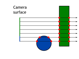
Orthographic camera. 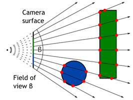
Perspective camera.


Figure 1: Camera models.
3.3 Ray casting
Now we have rays associated to every pixel of result image and we are able to compute intersections. By putting those two steps together we have a simple ray-caster (not ray-tracer yet).
Code listing 3 shows basic structure of the Intersection class. Every intersection stores information about the ray, ray parameter t, if it is entering or leaving ray, and some other things that will be discussed later.
Code listing 3: Intersection class.
1 2 3 4 5 6 7 8 9 10 11 12 13 14 15 16 | public class Intersection : IComparable<Intersection> { public IIntersectableObject IntersectedObject; public Ray Ray; public double RayParameter; public bool IsEnter; public bool InverseNormal; public Vector3 Position public double RayDistanceSqSigned; public Vector3 Normal; public Vector2 TextureCoord; public IMaterial Material; public object AdditionalData; } |
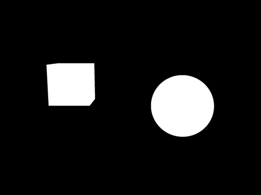
For every ray tries to intersect all objects in the scene and gather a list of intersections. Then simply discard all that have negative ray parameter because they are behind the camera. Now you can display white pixel if there are some intersections and black if they are not. You should see something similar to Figure 2.
Result of putting white pixel for intersection and black for no intersection.

Figure 2: Result of putting white pixel for intersection and black for no intersection.
3.4 Colors and textures
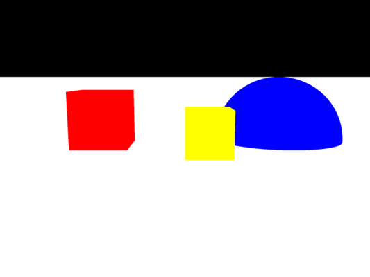
Black and white is not fun. Let's add some colors! If we look at the list of intersections for every ray we can choose the intersection which is closest to its origin. That's the one with the smallest positive ray parameter t. Now we can display a color based on the object which was hit. We know that because it is saved in the Intersection class. Figure 3 shows how a simple scene might look like.
Color based on the closest hit of the ray.

Figure 3: Color based on the closest hit of the ray.
Procedural textures are also simple. For 2D textures we have to compute texture coordinates. A texture coordinate is a 2D position on the surface. For a plane that's just position of the intersection. For a sphere it can be defined as longitude and latitude. Texture coordinates are usually defined from 0 to 1.
As an example Code listing 4 shows computation of texture coordinates on the sphere. They are computed in the CompleteIntersection method on the primitive object. We do not need to compute texture coordinates or normals for all intersections. Only the ones that are being used and displayed need the additional data. As an optimization the intersections are first filtered and then additional data is computed.
Code listing 4: Computation of texture coordinates on a sphere.
1 2 3 4 5 6 7 8 9 10 | public class Sphere : IIntersectableObject { public void CompleteIntersection(Intersection intersection) { Vector3 localIntPt = intersection.LocalIntersectionPt; intersection.Normal = localIntPt; intersection.TextureCoord.X = Math.Atan2(localIntPt.Z, localIntPt.X) / (2.0 * Math.PI) + 0.5; intersection.TextureCoord.Y = Math.Atan2(1, localIntPt.Y) / Math.PI; } } |
Based on the texture coordinate we can do some simple shapes like stripes or checkers. Just for completeness the code for checkers is in Code listing 5.
You might be asking: Can I use the 3D coordinate for some kind of 3D texture? The answer is yes, of course! It is maybe even simpler to do volumetric checkers, stripes or dots. As you can see the texturing method has access to the Intersection class so you can even use normal or ray parameter to do textures based on those! I am just sticking with traditional 2D textures for now.
Code listing 5: Checkers texture.
1 2 3 4 5 6 7 8 9 10 11 12 13 14 15 16 17 | public class CheckerTexture2D : ITexture { public double UFrequency { get; set; } public double VFrequency { get; set; } public ColorRgbt EvenColor { get; set; } public ColorRgbt OddColor { get; set; } public ColorRgbt GetColorAt(Intersection intersection) { double u = intersection.TextureCoord.X * UFrequency; double v = intersection.TextureCoord.Y * VFrequency; long ui = (long)Math.Floor(u); long vi = (long)Math.Floor(v); return ((ui + vi) & 1) == 0) ? EvenColor : OddColor; } } |
Example scene with textured objects is show in Figure 4. Thanks to the textures you can see the perspective and the objects much better even though there are no lights and shadows in the scene.
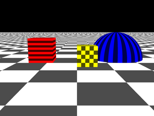
Example of simple scene with textures.
