April 2013
Real time visualization of 3D vector field with CUDA
3 Visualization using glyphs
3.1 Line glyphs for VF visualization
Code listing 1: Simplified CUDA kernel for computation of glyph lines
1 2 3 4 5 6 7 8 9 10 11 12 13 14 15 16 17 18 19 20 21 22 | __global__ void glyphLinesKernel(float x, uint2 glyphsCount, float2 worldSize, float3* outVertices, float3* outColors) { uint id = __umul24(blockIdx.x, blockDim.x) + threadIdx.x; uint totalCount = __umul24(glyphsCount.x, glyphsCount.y); if (id >= totalCount) { return; } float y = (id % glyphsCount.x) * (worldSize.x / glyphsCount.x); float z = (id / glyphsCount.x) * (worldSize.y / glyphsCount.y); float4 vector = tex3D(vectorFieldTex, x, y, z); id *= 2; outVertices[id] = make_float3(x, y, z); outVertices[id + 1] = make_float3(x, y, z) + normalize(make_float3(vector.x, vector.y, vector.z)) * vector.w; float4 color = tex1D(vectorMangitudeCtfTex, vector.w); outColors[id] = make_float3(color.x, color.y, color.z); outColors[id + 1] = make_float3(color.x, color.y, color.z); } |
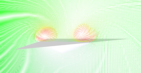
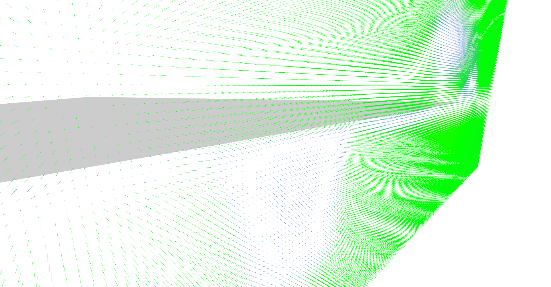
Line glyphs reveals two vortices above the sides of the wing. 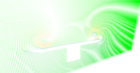
Line glyphs near the end of the wing - main vortices are weaker and you may notice very small secondary vortices. 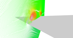
Detail on primary and secondary vertices above the sides of the wing. 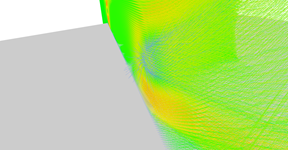
Detail on recirculation bubble where wind goes even backwards.
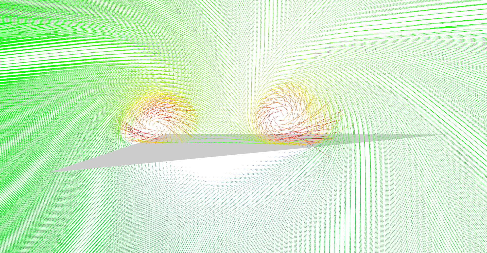
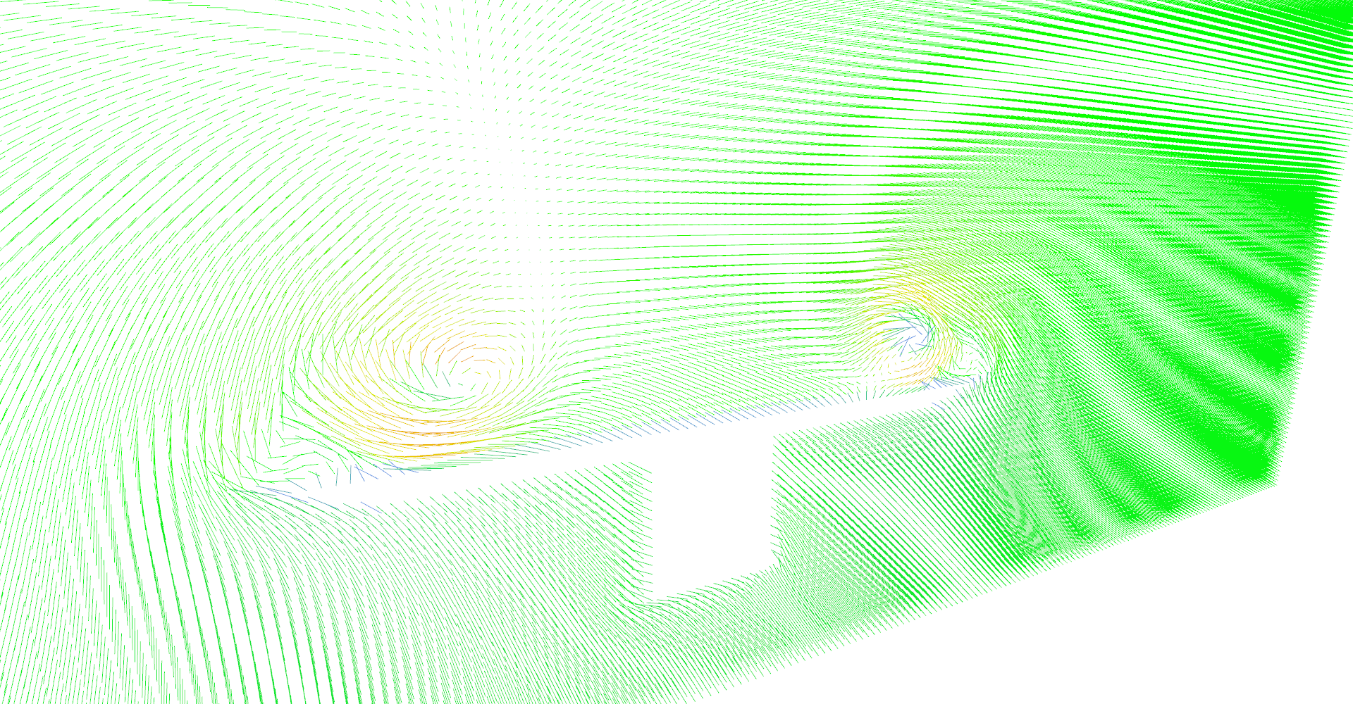


Figure 1: Vector field visualization using line glyphs
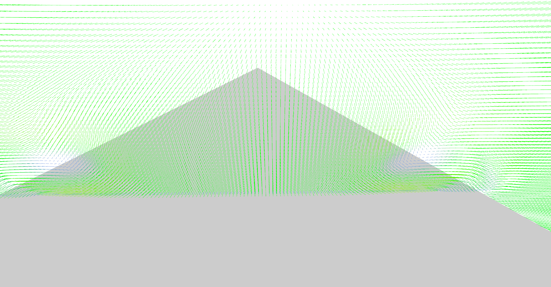
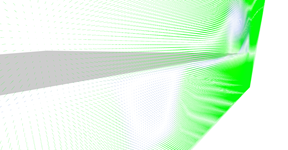
It is possible to set number of glyph lines in plane to very high numbers and create solid wall as shown in Figure 2. This serves as relatively nice visualization of vector magnitudes.
High density line glyphs plane effectively visualizing magnitude field. Plane is just behind the front of the wing. 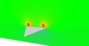
Vector field magnitudes near the middle of the wing. 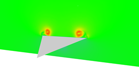
Vector field magnitudes near the middle of the wing. 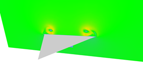
Vector field magnitudes near the end of the wing. 
Vector field magnitudes near the end of the wing. 
Vector field magnitudes just behind the wing. 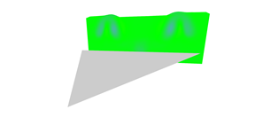
Vector field magnitudes further behind the wing. 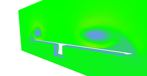
Vector field magnitudes near the end of the wing. Wing itself is not shows which reveals box under the wing. Notice that wind is slower near the surface of the wing.


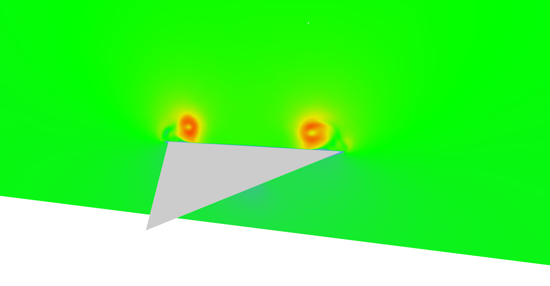

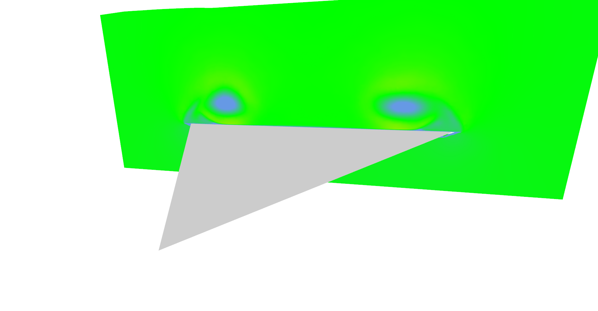
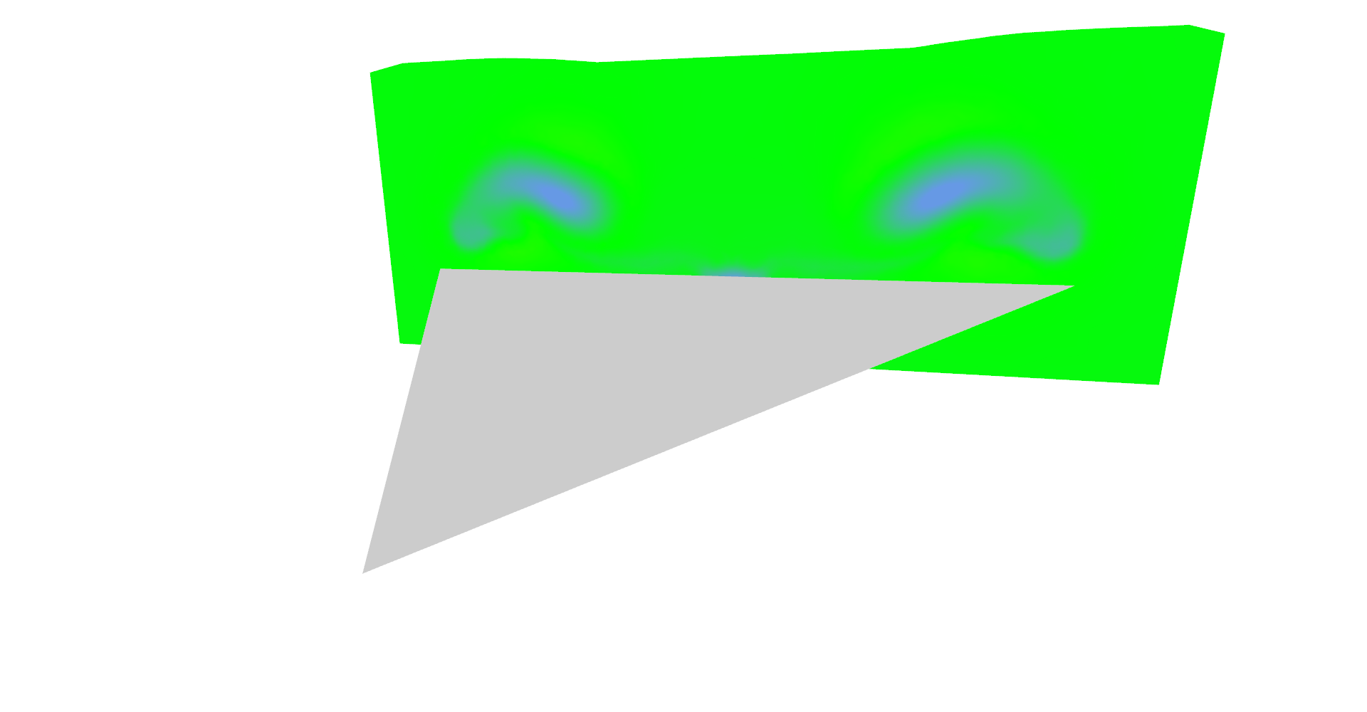


Figure 2: Magnitude visualization using high density of line glyphs.
3.2 Arrow glyphs for VF visualization
Code listing 2: Simplified CUDA kernel for computation of glyph arrows
1 2 3 4 5 6 7 8 9 10 11 12 13 14 15 16 17 18 19 20 21 22 23 24 25 26 27 28 29 30 31 32 33 34 35 36 37 38 39 40 41 42 43 44 45 46 47 48 49 50 51 52 53 | __global__ void glyphArrowsKernel(float x, uint2 glyphsCount, float2 worldSize, float3* outVertices, uint3* outFaces, float3* outVertexNormals, float3* outVertexColors) { uint id = __umul24(blockIdx.x, blockDim.x) + threadIdx.x; // ... same part as in lines kernel ... float4 vector = tex3D(vectorFieldTex, x, y, z); float3 forward = normalize(make_float3(vector.x, vector.y, vector.z)); float3 xAxis = normalize(findPerpendicular(forward)); float3 yAxis = normalize(cross(forward, xAxis)); uint faceId = id * 6; uint vertId = id * 9; outFaces[faceId] = make_uint3(vertId, vertId + 1, vertId + 2); outFaces[faceId + 1] = make_uint3(vertId, vertId + 2, vertId + 3); outFaces[faceId + 2] = make_uint3(vertId, vertId + 3, vertId + 4); outFaces[faceId + 3] = make_uint3(vertId, vertId + 4, vertId + 1); outFaces[faceId + 4] = make_uint3(vertId + 5, vertId + 6, vertId + 7); outFaces[faceId + 5] = make_uint3(vertId + 5, vertId + 7, vertId + 8); id *= 9; outVertexNormals[id] = forward; outVertexNormals[id + 1] = xAxis; outVertexNormals[id + 2] = yAxis; outVertexNormals[id + 3] = -xAxis; outVertexNormals[id + 4] = -yAxis; forward *= -1; outVertexNormals[id + 5] = forward; outVertexNormals[id + 6] = forward; outVertexNormals[id + 7] = forward; outVertexNormals[id + 8] = forward; forward *= vector.w; xAxis *= 0.1; yAxis *= 0.1; outVertices[id] = position - forward; // Forward was multiplied by -1. outVertices[id + 1] = position + xAxis; outVertices[id + 2] = position + yAxis; outVertices[id + 3] = position - xAxis; outVertices[id + 4] = position - yAxis; outVertices[id + 5] = position + xAxis; outVertices[id + 6] = position + yAxis; outVertices[id + 7] = position - xAxis; outVertices[id + 8] = position - yAxis; float4 color = tex1D(vectorMangitudeCtfTex, vector.w); float3 color3 = make_float3(color.x, color.y, color.z); for (int i = 0; i < 9; ++i) { outVertexColors[id + i] = color3; } } |
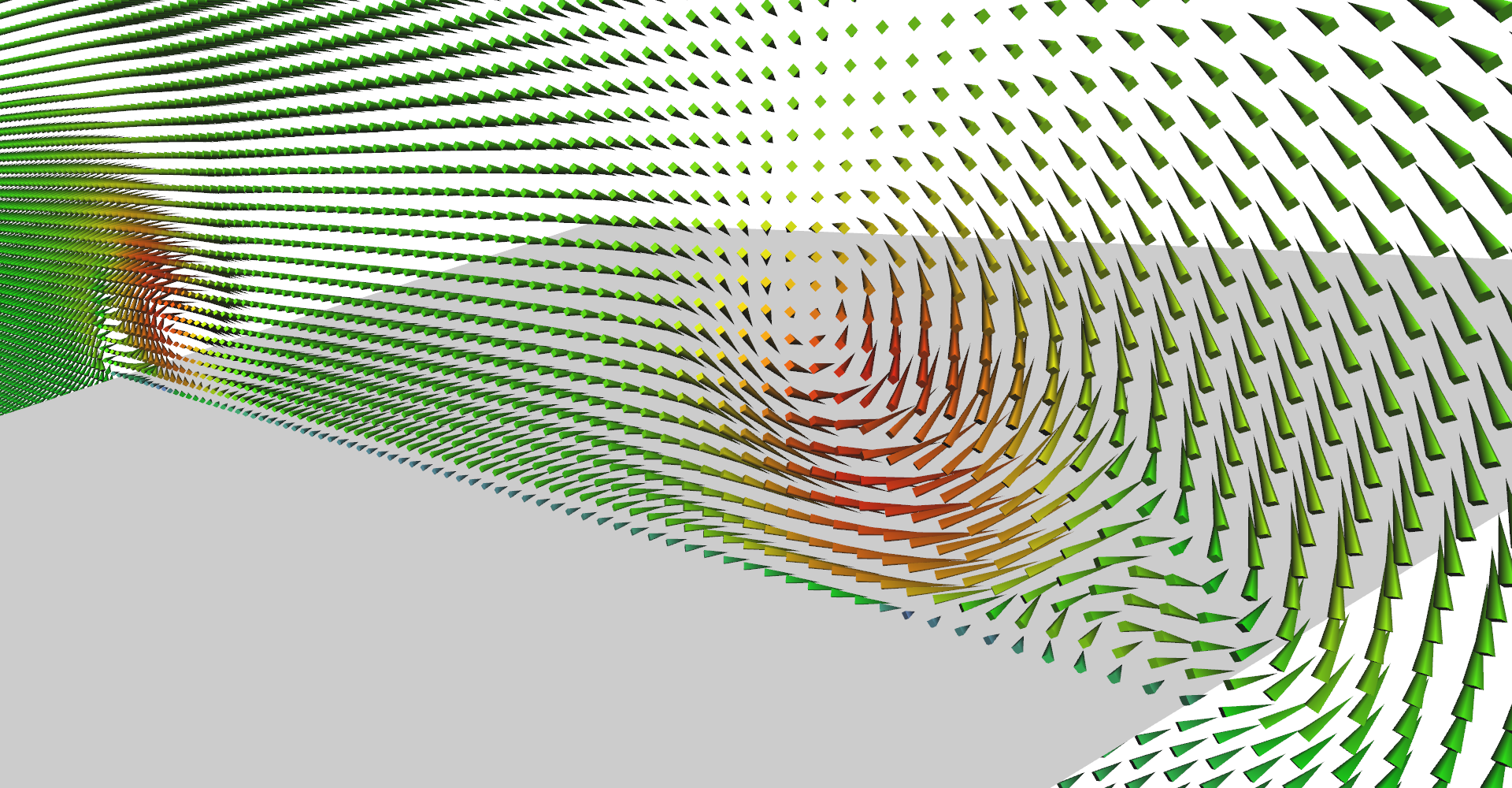
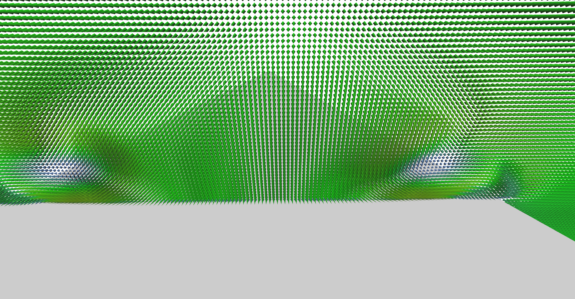
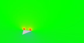
Vector field visualization using arrow glyphs near the end of the wing. 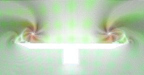
Front view of glyphs plane going through the middle of the wing. Notice secondary vortices under the primary ones. 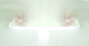
Lower density of arrow glyphs. 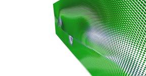
Glyphs plane just behind the delta-wing. 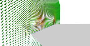
Another view on glyph plane from the back. 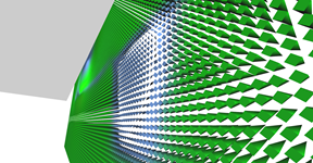
Detail on the area behind the aerodynamic box of the wing where air is going in the opposite direction (the box is not shown).

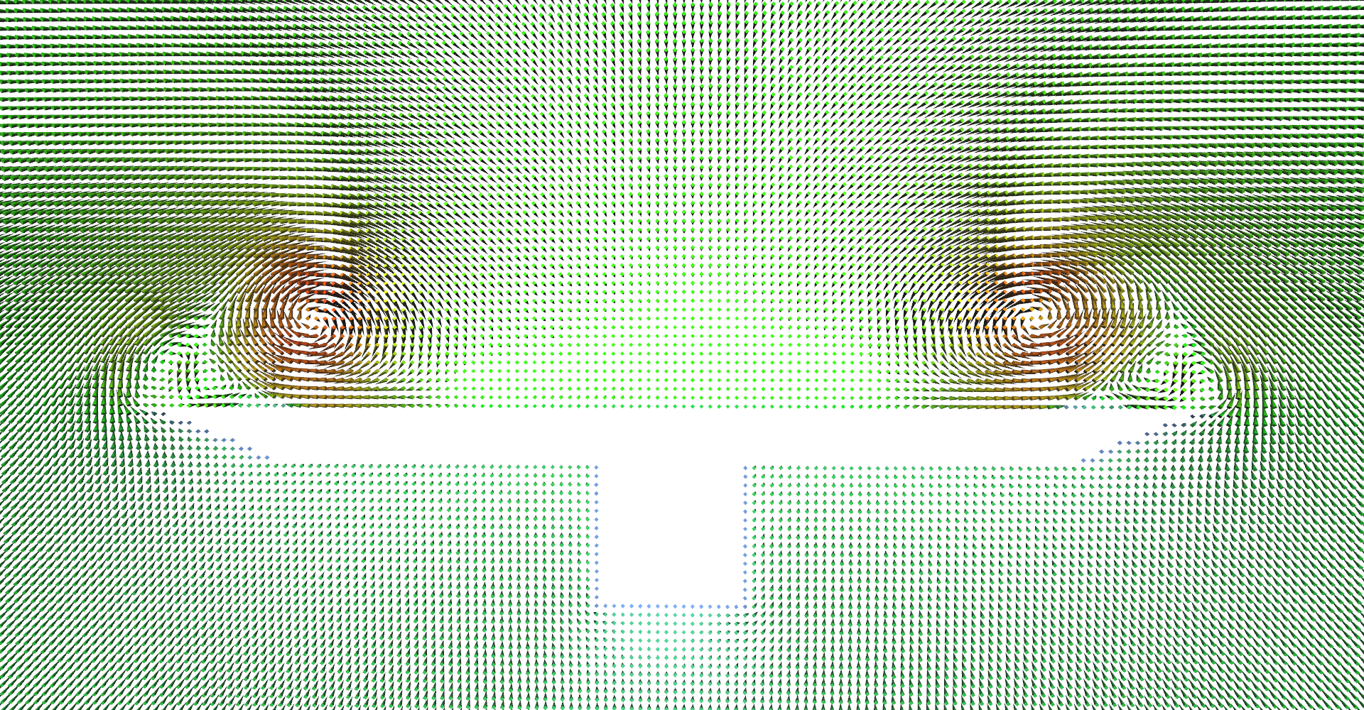
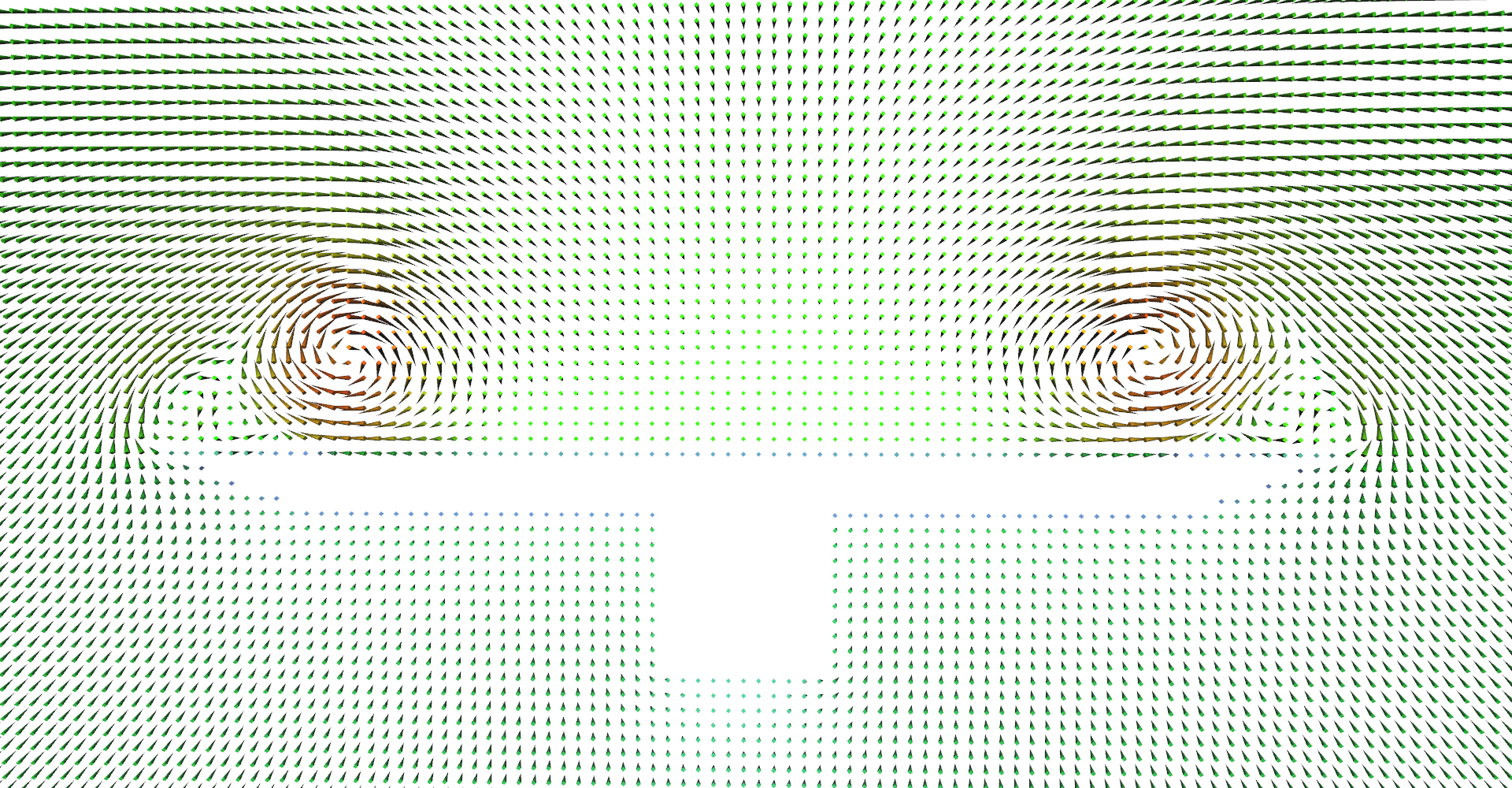

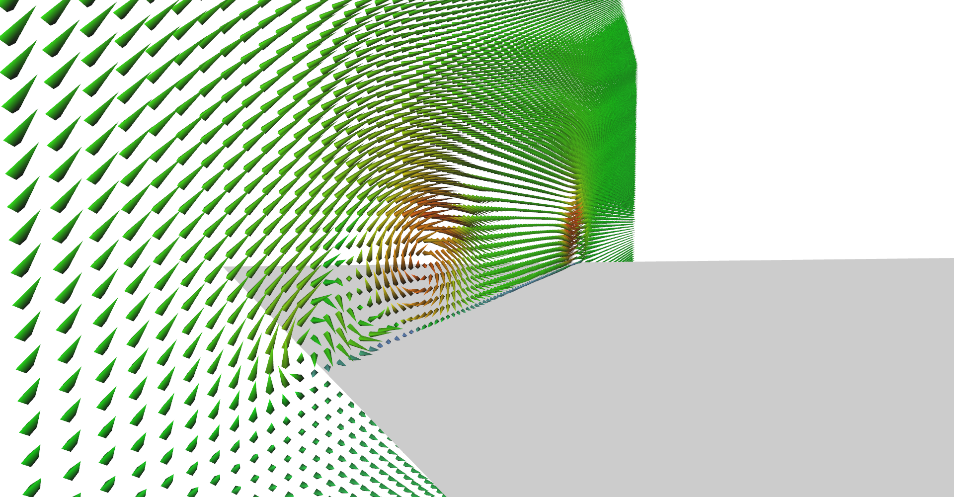
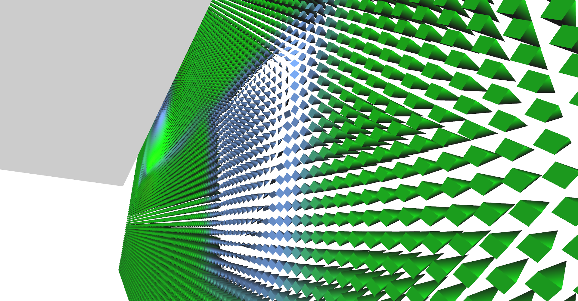
Figure 3: Vector field visualization using line glyphs.
3.3 Line vs. arrow glyphs
Line vs. arrow glyphs (pair 1, lines). 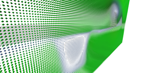
Line vs. arrow glyphs (pair 1, arrows). 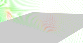
Line vs. arrow glyphs (pair 2, lines). 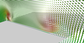
Line vs. arrow glyphs (pair 2, arrows). 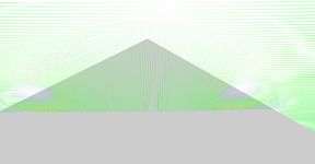
Line vs. arrow glyphs (pair 3, lines). 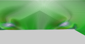
Line vs. arrow glyphs (pair 3, arrows).