April 2013
Real time visualization of 3D vector field with CUDA
5 Visualization using stream lines and stream tubes
5.1 Stream lines
Code listing 1: Simplified CUDA kernel for evaluation of stream lines
1 2 3 4 5 6 7 8 9 10 11 12 13 14 15 16 17 18 19 20 21 22 23 24 25 26 27 28 29 30 31 32 33 34 35 36 37 38 39 40 41 42 43 44 45 46 47 48 49 50 51 | __global__ void computeStreamlinesLineKernel(float3* seeds, uint seedsCount, double dt, uint maxSteps, cudaExtent volumeSize, uint geometrySampling, float3* outVertices, uint* outComputedSteps, float3* outVertexColors) { uint id = __umul24(blockIdx.x, blockDim.x) + threadIdx.x; if (id >= seedsCount) { return; } uint outIndex = id * (maxSteps / geometrySampling + 1); // Integration is double precision. double3 position = make_double3(seeds[id].x, seeds[id].y, seeds[id].z); outVertices[outIndex].x = (float)position.x; outVertices[outIndex].y = (float)position.y; outVertices[outIndex].z = (float)position.z; ++outIndex; uint geometryStep = geometrySampling; uint step = 1; for (; step < maxSteps; ++step) { if (position.x < 0 || position.y < 0 || position.z < 0 || position.x > volumeSize.width || position.y > volumeSize.height || position.z > volumeSize.depth) { break; } double4 dv = rk4Integrate(position, dt); position.x += dv.x; position.y += dv.y; position.z += dv.z; --geometryStep; if (geometryStep == 0) { geometryStep = geometrySampling; outVertices[outIndex].x = (float)position.x; outVertices[outIndex].y = (float)position.y; outVertices[outIndex].z = (float)position.z; setColorTo(outVertexColors[outIndex - 1], (float)dv.w); ++outIndex; } } // Color of the last line point. outVertexColors[outIndex - 1] - outVertexColors[outIndex - 2]; // Save the number of computed line segments. outComputedSteps[id] = step / geometrySampling; } |

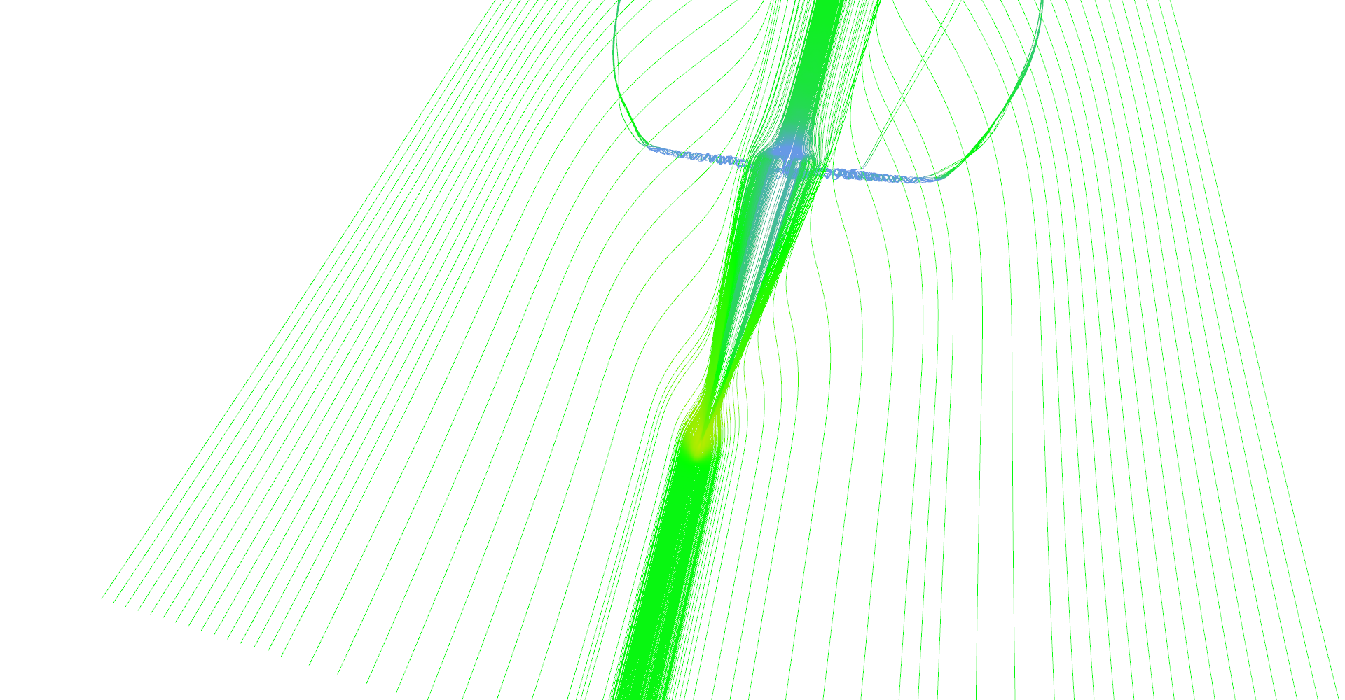
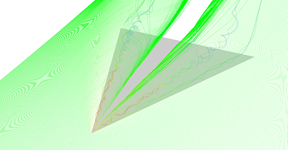
Stream lines seeded at very small area near the tip of the wing. Primary and secondary vortices are nicely visible as well as air moving sideways behind the edge of the wing. 
Slightly different setup as previous image. 
Stream lines seeded at long line in front of the wing. 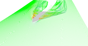
Slightly different setup as previous image.
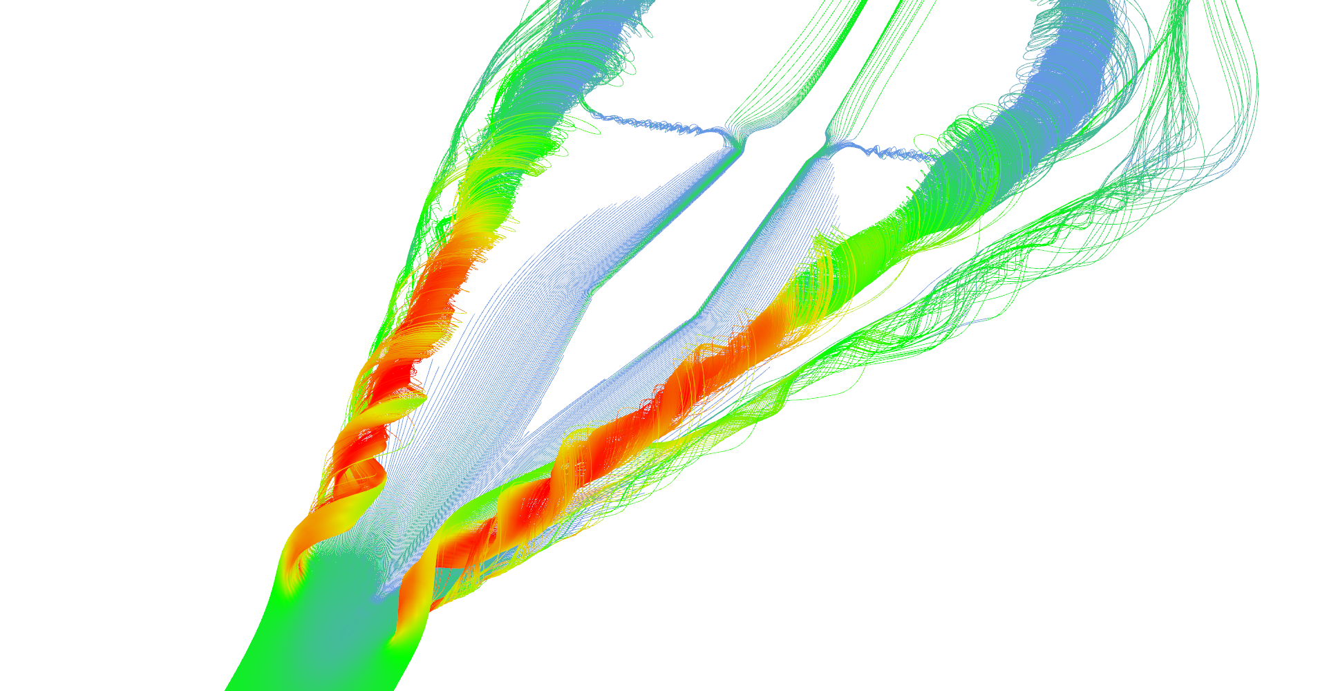
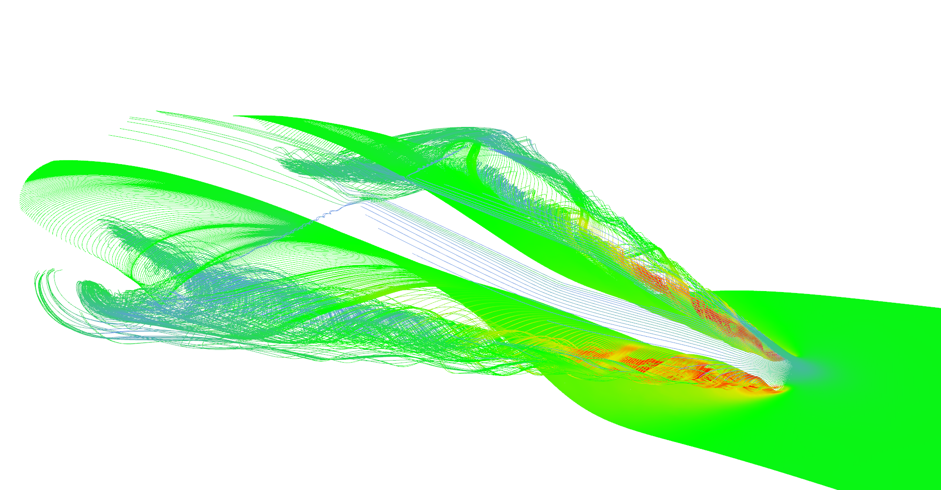

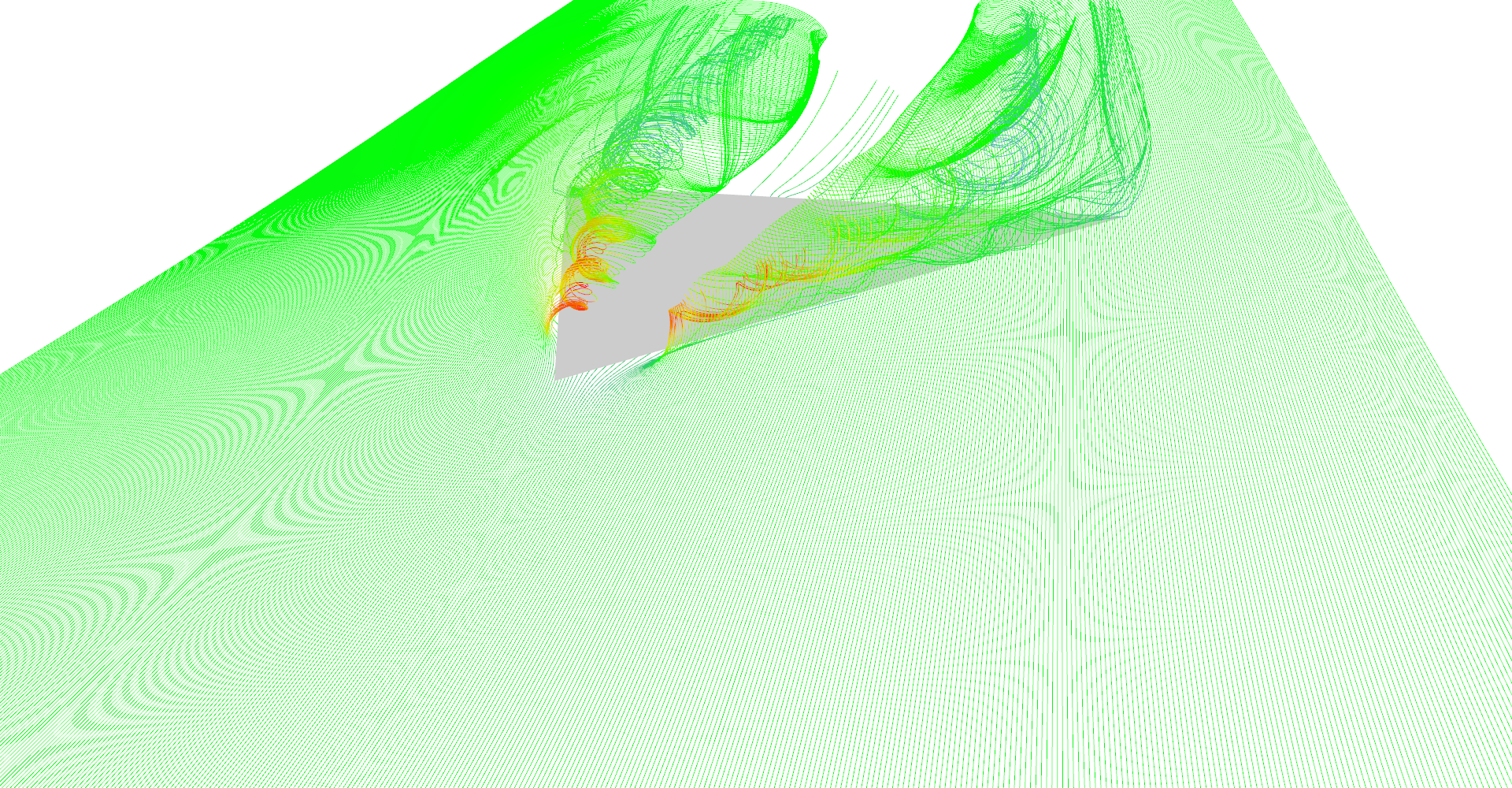
Figure 1: Stream lines visualization.
5.2 Stream tubes
Code listing 2: Kernels for construction of stream tubes
1 2 3 4 5 6 7 8 9 10 11 12 13 14 15 16 17 18 19 20 21 22 23 24 25 26 27 28 29 30 31 32 33 34 35 36 37 38 39 40 41 42 43 44 45 46 47 48 49 50 51 | __device__ void createTubeBaseVertices(float3 pos, float3 v, float radius, uint baseIndex, float3 color, float3* outVetrices, float3* outNormals, float3* outColors) { float3 xAxis = normalize(findPerpendicular(v)); float3 yAxis = normalize(cross(v, xAxis)); // x * cos(0) + y * sin(0) outNormals[baseIndex] = xAxis; outVetrices[baseIndex] = pos + xAxis * radius; outColors[baseIndex] = color; ++baseIndex; // x * cos(72) + y * sin(72) v = 0.3090f * xAxis + 0.9511f * yAxis; outNormals[baseIndex] = v; outVetrices[baseIndex] = pos + v * radius; outColors[baseIndex] = color; ++baseIndex; // x * cos(144) + y * sin(144) v = -0.8090f * xAxis + 0.5878f * yAxis; outNormals[baseIndex] = v; outVetrices[baseIndex] = pos + v * radius; outColors[baseIndex] = color; ++baseIndex; // x * cos(216) + y * sin(216) v = -0.8090f * xAxis - 0.5878f * yAxis; outNormals[baseIndex] = v; outVetrices[baseIndex] = pos + v * radius; outColors[baseIndex] = color; ++baseIndex; // x * cos(288) + y * sin(288) v = 0.3090f * xAxis - 0.9511f * yAxis; outNormals[baseIndex] = v; outVetrices[baseIndex] = pos + v * radius; outColors[baseIndex] = color; } __device__ void createTubeIndices(uint vertexBaseId, uint baseFaceId, uint3* outFaces) { for (uint i = 0; i < 5; ++i) { uint iNext = (i + 1) % 5; outFaces[baseFaceId++] = make_uint3(vertexBaseId + i, vertexBaseId + iNext, vertexBaseId - 5 + iNext); outFaces[baseFaceId++] = make_uint3(vertexBaseId + i, vertexBaseId - 5 + i, vertexBaseId - 5 + iNext); } } |
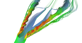
Stream tubes showing the main features of the delta-wing dataset - primary and secondary vortices and air going sideways behind the back edge of the wing. 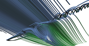
Detail on the back of the wing from the bottom. You can clearly see the vortex behind the box on the wing (the wing and the box is not shown). 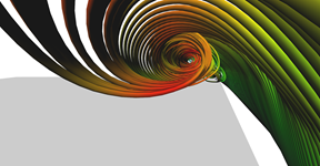
Detail of the primary vortex. 
Another visualization of the datasets using stream-tubes. 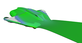
Air hitting the bottom of the wing revealing the aerodynamic box. Notice how air rolls over the edges of the box. 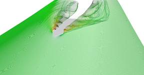
Another visualization of the datasets using stream-tubes. 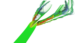
Narrow stream of air hitting the tip of the wing. 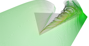
Row of stream-tubes seeded among the wing edge. 
Recirculation bubble visualization. 
Vertical seeding of stream-tubes.


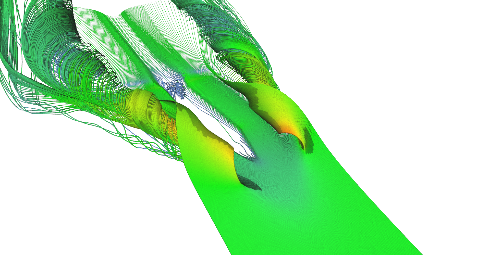

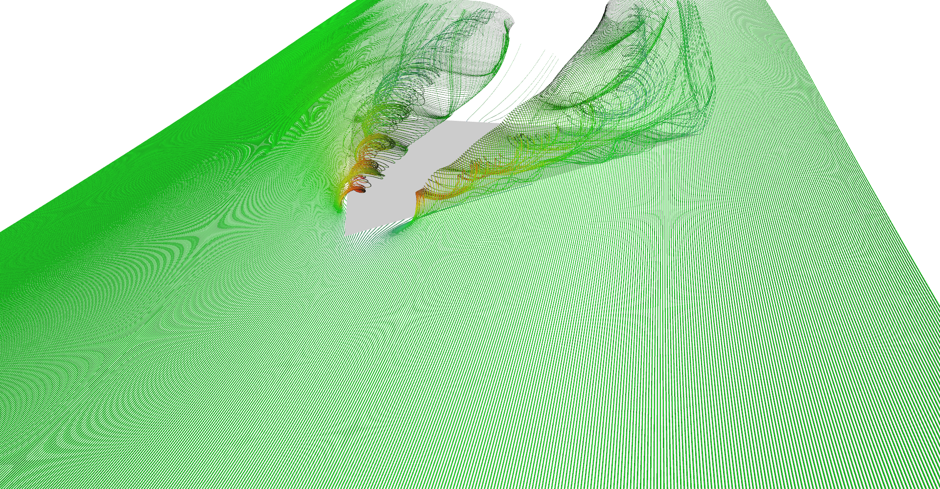

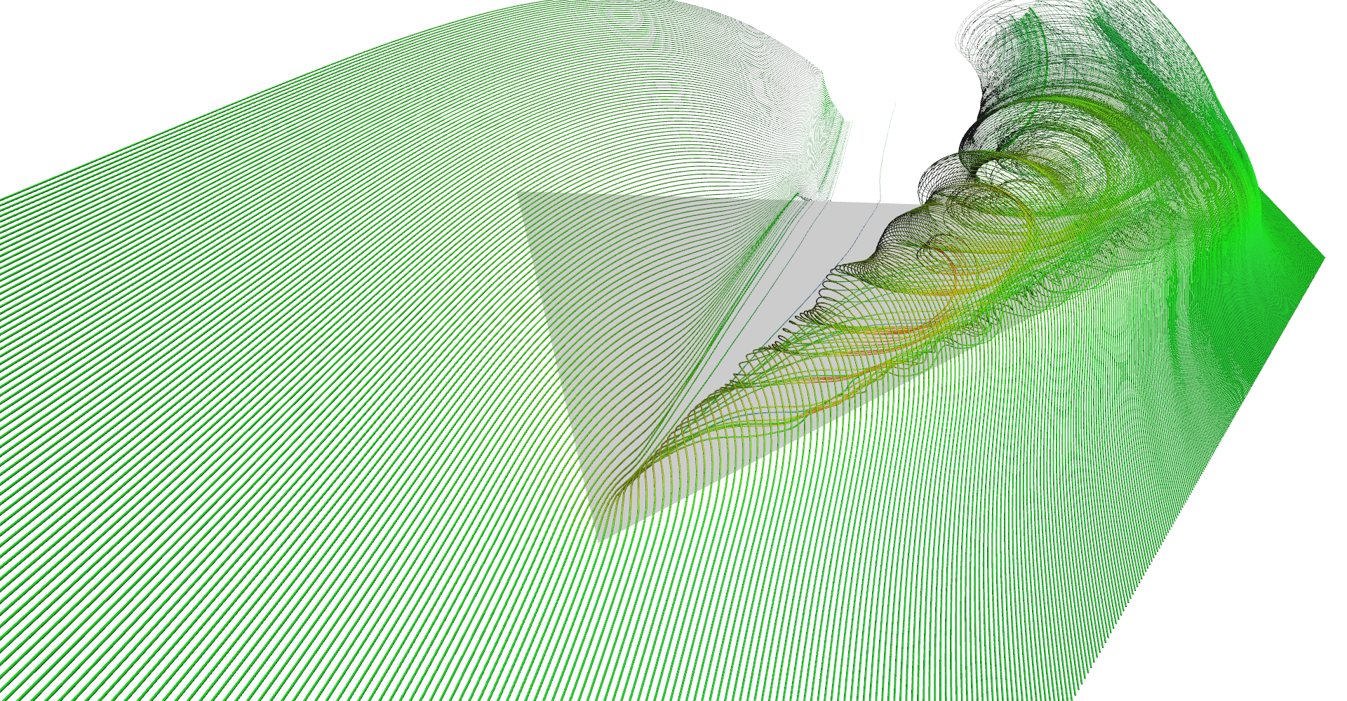
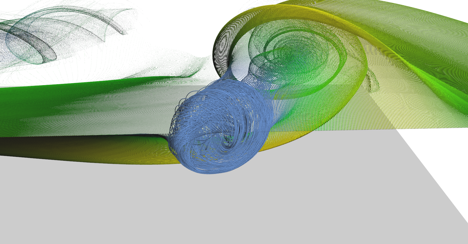
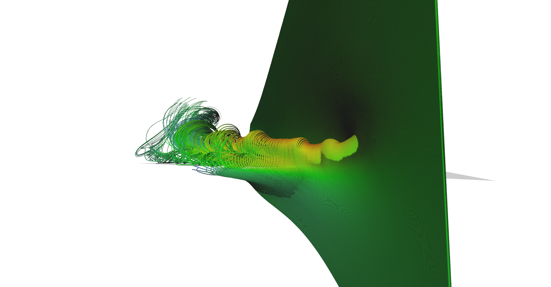
Figure 2: Stream tubes visualization.
5.3 Adaptive stream lines
Regular vs. adaptive (pair 1, regular). 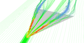
Regular vs. adaptive (pair 1, adaptive). Area near the tip of the wing is sampled much more because air is forming vortices there. 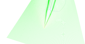
Regular vs. adaptive (pair 2, regular). 
Regular vs. adaptive (pair 2, adaptive). Adaptive seeding revealed important features. 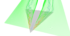
Regular vs. adaptive (pair 3, regular). 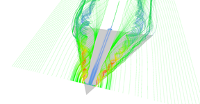
Regular vs. adaptive (pair 3, adaptive). 
Regular vs. adaptive (pair 4, regular). 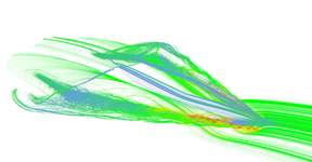
Regular vs. adaptive (pair 4, adaptive). 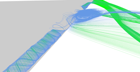
Regular vs. adaptive (pair 5, regular). 
Regular vs. adaptive (pair 5, adaptive).
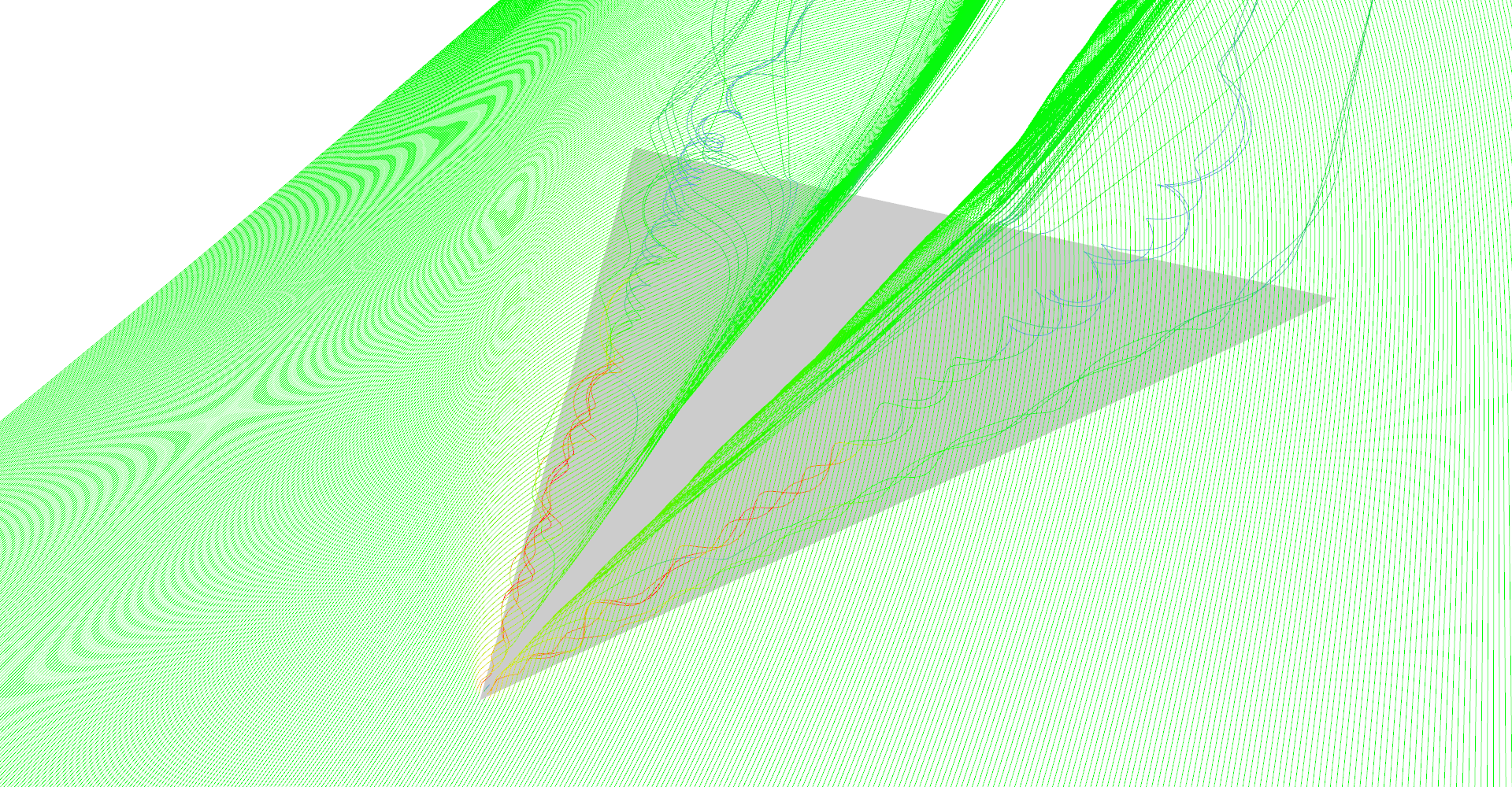


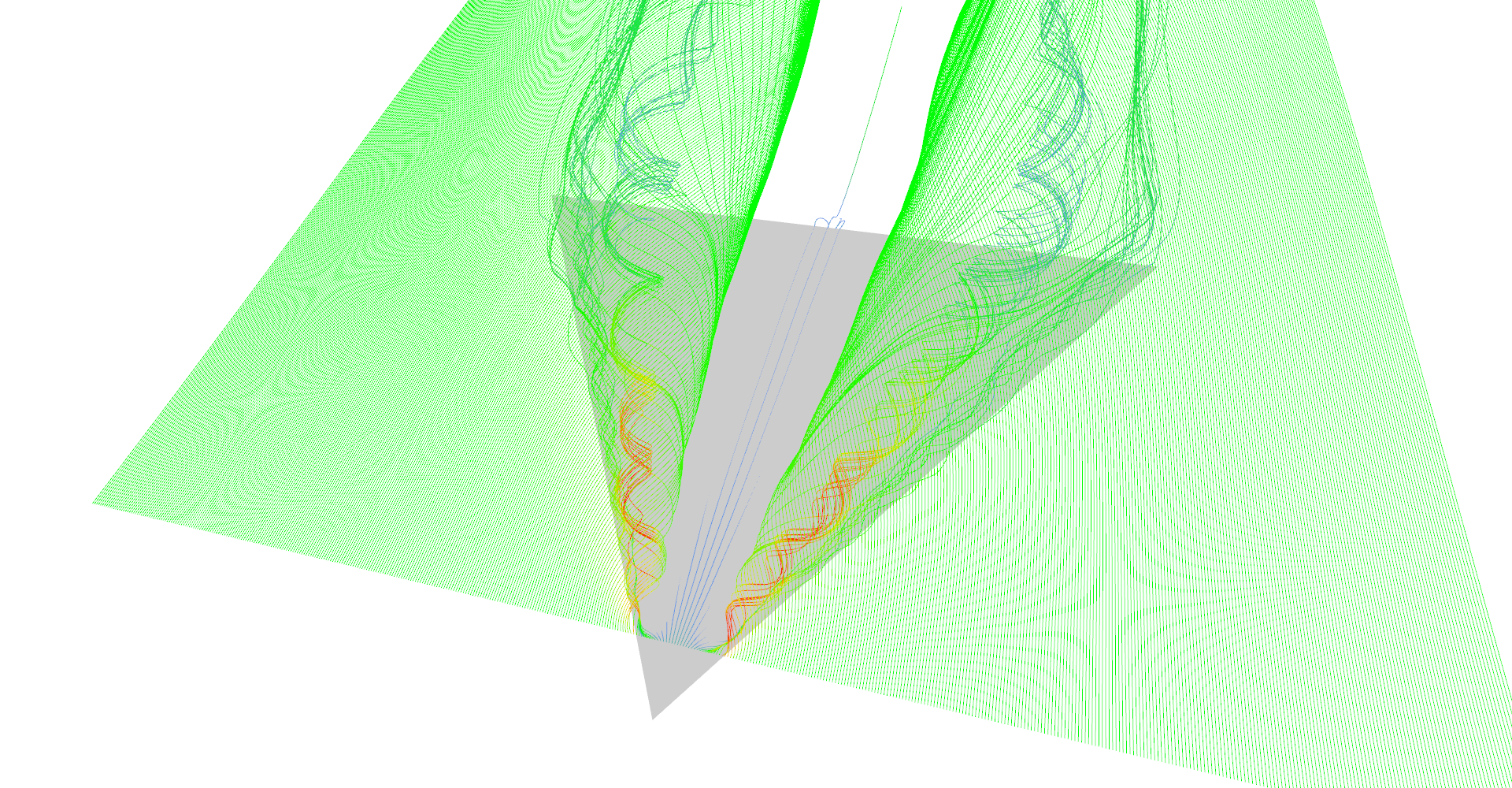


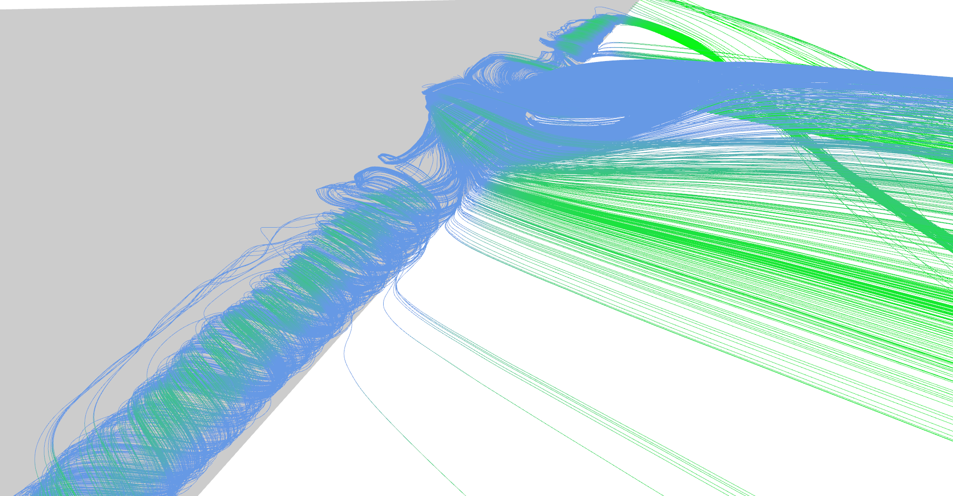
Figure 3: Comparison between regular and adaptive stream line seeding.
Code listing 3: Kernels for construction of stream tubes
1 2 3 4 5 6 7 8 9 10 11 12 13 14 15 16 17 18 19 20 21 22 23 24 25 26 27 28 29 30 31 32 33 34 35 36 37 38 39 40 41 42 43 44 45 46 47 48 49 50 51 52 53 54 55 56 | __global__ void computeLineAdaptiveExtensionKernel( float maxAllowedLineDist, uint2* linePairs, uint linePairsCount, float3* lineVertices, uint verticesPerLine, uint verticesPerSample, uint* lineLengths, float3* seeds, uint2* outLinePairs, uint* outPairsIndex, uint* outLinesIndex, uint linesMaxCount) { uint id = __umul24(blockIdx.x, blockDim.x) + threadIdx.x; if (id >= linePairsCount) { return; } uint2 currPair = linePairs[id]; uint outPairIndex = atomicAdd(outPairsIndex, 1); // Preserve original pair. outLinePairs[outPairIndex].x = currPair.x; outLinePairs[outPairIndex].y = currPair.y; uint count = min(lineLengths[currPair.x], lineLengths[currPair.y]); if (count < 2) { return; // One of lines too short. } // Test 32 samples for divergence. float maxDist = 0; for (uint i = 0; i < count; i += count / 32) { float3 v1 = lineVertices[currPair.x * verticesPerLine + i * verticesPerSample]; float3 v2 = lineVertices[currPair.y * verticesPerLine + i * verticesPerSample]; maxDist = max(maxDist, length(v1 - v2)); } if (maxDist < maxAllowedLineDist) { return; // Lines do not diverged. } uint newLines = (uint)sqrtf(maxDist / maxAllowedLineDist); uint outLineIndex = atomicAdd(outLinesIndex, newLines); if ((outLineIndex + newLines) >= linesMaxCount) { atomicAdd(outLinesIndex, -newLines); return; // Not enough space for new seeds. } float3 seedStep = (seeds[currPair.y] - seeds[currPair.x]) / (newLines + 1); uint lastOutPairIndex = outPairIndex; for (uint i = 0; i < newLines; ++i) { seeds[outLineIndex + i] = seeds[currPair.x] + (i + 1) * seedStep; // Insert new pair (like in linked-list). uint outPairIndex = atomicAdd(outPairsIndex, 1); outLinePairs[lastOutPairIndex].y = outLineIndex + i; outLinePairs[outPairIndex].x = outLineIndex + i; outLinePairs[outPairIndex].y = currPair.y; lastOutPairIndex = outPairIndex; } } |
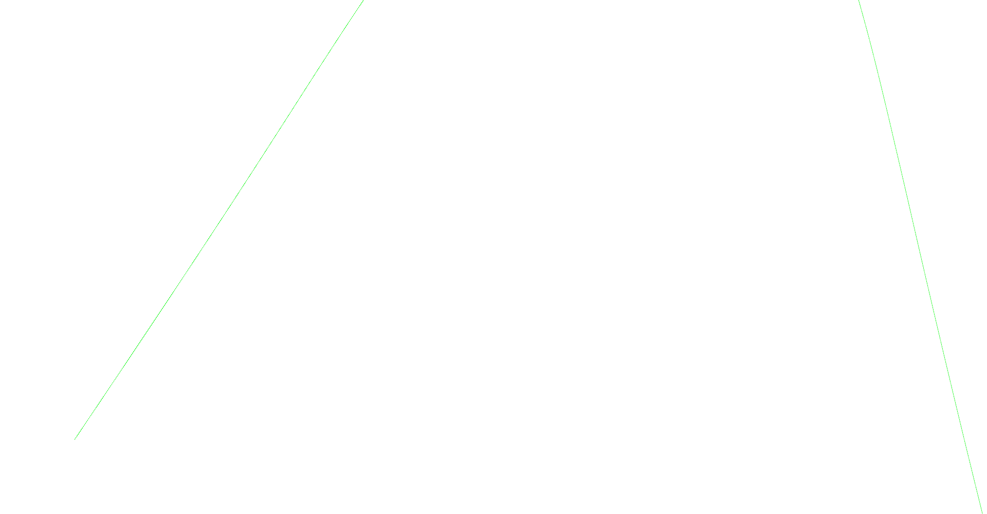
Step 1 of adaptive seeding algorithm. 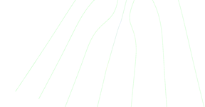
Step 2 of adaptive seeding algorithm. 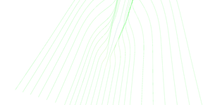
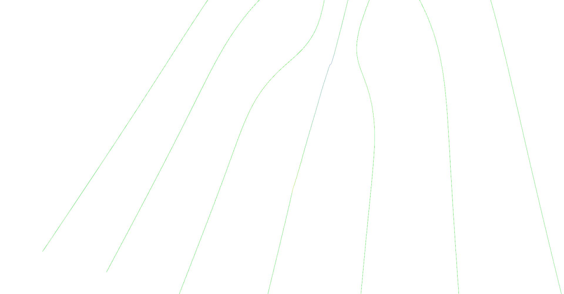
Step 3 of adaptive seeding algorithm. 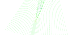
Step 4 of adaptive seeding algorithm. 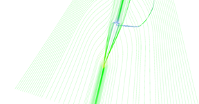
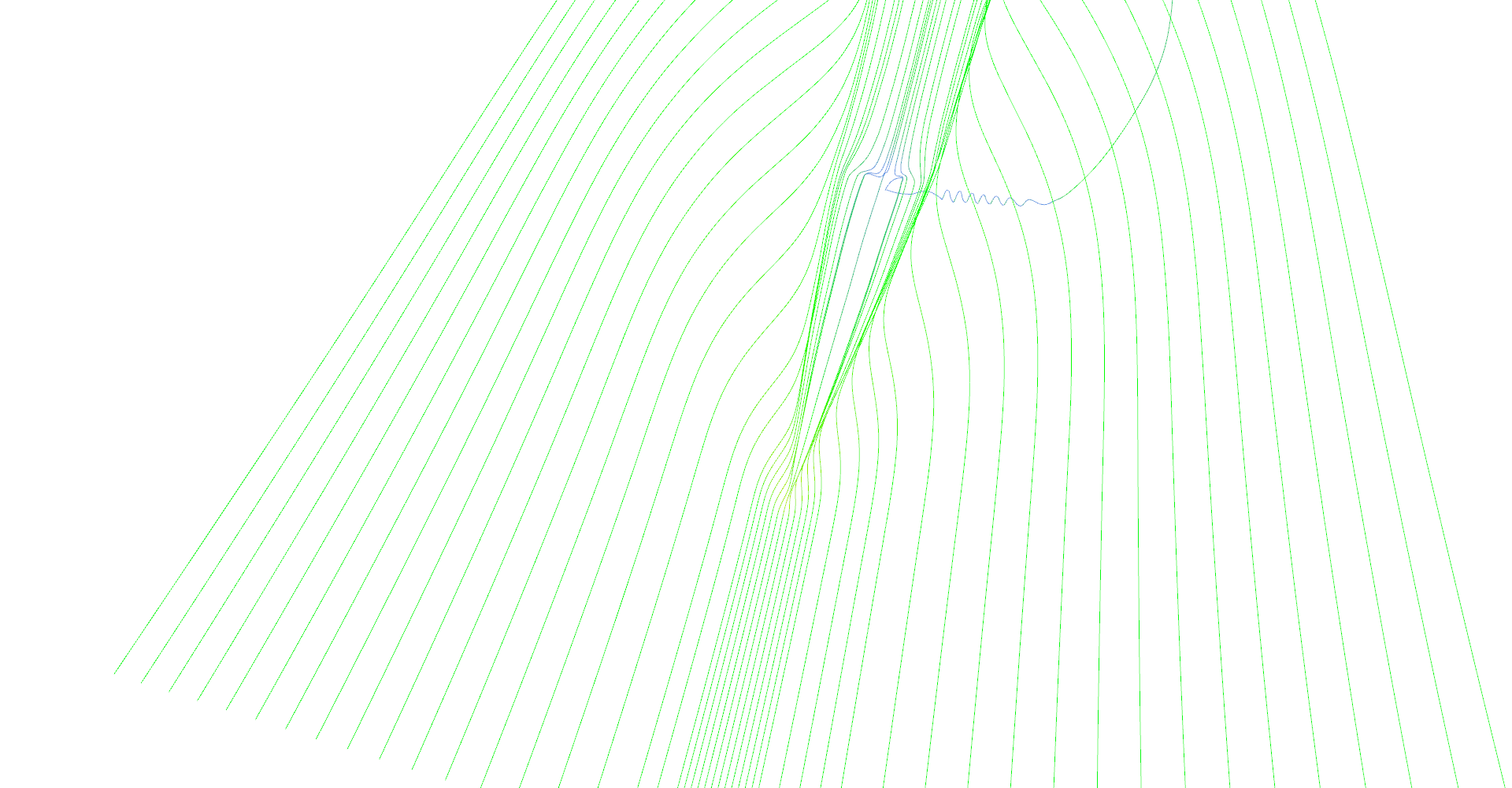
Step 5 of adaptive seeding algorithm. 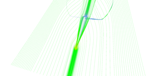
Step 6 of adaptive seeding algorithm. 
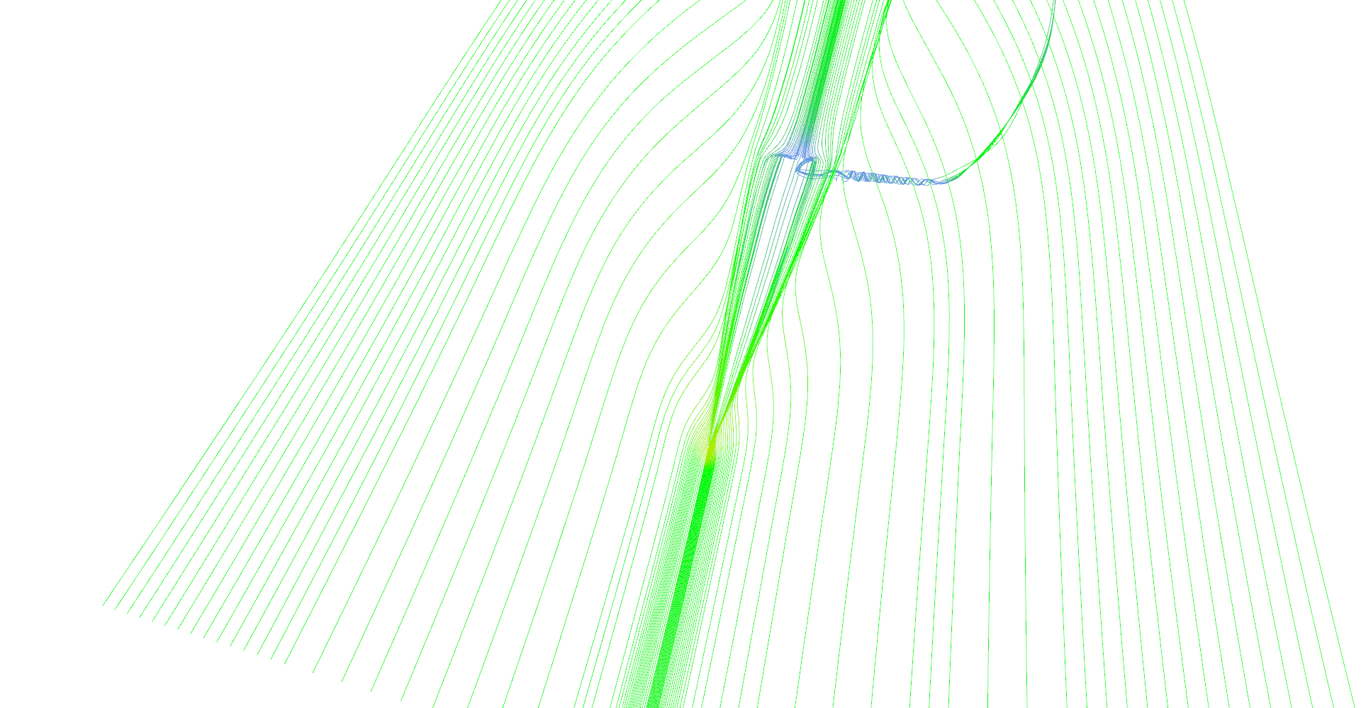
Step 7 of adaptive seeding algorithm. 
Step 8 of adaptive seeding algorithm.